 KO
Semiconductor · Equipment
Inspection and Vision Systems
Optical inspection for semiconductor packaging — standalone 2D/3D inspection machines for package strips, stacked packages, image sensor packages and wafers, plus vision systems that run inside other equipment on the line.
Two kinds of machine. Standalone inspection systems are their own station on the line and sort the material themselves. Vision systems are PC-based units fitted inside someone else’s equipment — a trim press, a singulation press, a marking machine — inspecting in-line and reporting the result back to that machine.
Where a defect is a height or a depth rather than a difference in brightness, flat 2D imaging cannot see it. Synapse combines 2D and 3D measurement so that swelling, dent, void and tilt are caught as measured values rather than guessed at from contrast.
Package Inspection Systems
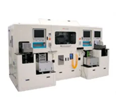
Package Substrate Inspection
Inspects a package strip on both faces after moulding. The mould face is checked for unfilled areas, voids, cracks and exposed base metal, and the mould thickness is measured; the PCB face is checked for land contamination, swelling and dent, and heavy flash. Both faces use 2D and 3D together, so the defects that flat imaging misses are measured instead of inferred.
Defect positions come out with the package index, so a bad unit can be traced. Every measurement is kept in the database, and process capability indices are calculated from it.
| Inspection target | IC package strip after moulding |
| Mould-side defects | Incomplete mould, void, crack, exposed base metal, mould thickness |
| PCB-side defects | Swelling, dent, contaminated land, heavy flash |
| Strip size | 100 × 260 mm – 30 × 170 mm |
| Cycle time | < 50 sec for an 80 × 270 mm strip |
| Stages | 2D/3D mould · 2D PCB · 3D PCB |
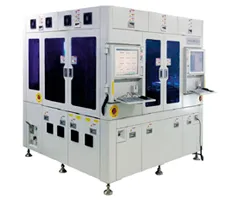
Stacked Package Inspection
For stacked packages that have been through reflow and sit on a boat. The machine picks each one up, measures total height, gap and misalignment, and inspects all four side faces before sorting good from bad. Accuracy is at the micrometre level.
The unit map of the boat is returned with the result, so the line knows which position failed.
| Inspection target | Stacked IC package after reflow |
| Speed | Over 6,000 UPH |
| Defects | Package broken, void, PCB damage, PCB broken, PCB delamination, misalignment |
| Option | Total height measurement |
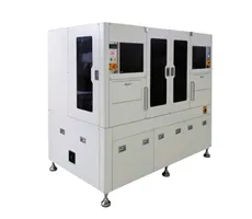
Image Sensor Package Inspection
For CMOS image sensor assembly, where the defect that matters is the size of a single pixel. Two points in the process are covered: the sensor die surface after die bonding, while the units are still on the PCB strip, and the cover glass and die surfaces once the packages are loaded into a tray.
Auto-focus lets each layer be inspected in turn at full resolution rather than compromising on one focal plane.
| Inspection target | CMOS image sensor package |
| Glass, top | Stabbing, stuck particle, scratch, crack, tilt |
| Glass, bottom | Stabbing, bubble, particle, scratch |
| Die, top | Particle, smearing, scratch, die tilt |
| Inspection time | Under 4 sec per die; under 8 sec per package, glass and die |
| Machine size | Approx. 2,400 (W) × 1,500 (L) × 1,700 (H) mm |
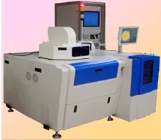
Wafer Inspection
Optical inspection of the wafer cell surface. Foreign material, breakage, chip-out, scratches, probe marks and discolouration are detected automatically, down to two micrometres.
The Z axis compensates itself to hold focus across the wafer, and results are kept as a defect cell map with wafer tracking and SPC on top.
| Wafer size | 4–8 inch or 8–12 inch |
| Cassette | 25 ea |
| Defects | Foreign material, scratch, probe mark, discolour, broken, chip-out |
| Minimum defect size | 2 μm |
| Inspection time | 90 sec for 8 inch · 200 sec for 12 inch |
| Changeover | 10–20 min |
| Pass yield | 99.8 % — over-kill 0.2 %, under-kill 0.0 % |
| Machine size | Approx. 1,570 × 1,150 × 1,620 mm, approx. 1,400 kg |
In-Line Vision Systems
PC-based vision units that mount inside production equipment and inspect as the machine runs, passing the verdict — and where needed a position correction — back to the host machine.
Trim
Checks lead and dambar quality before and after the press removes the junk and dambar joining the leads of a lead frame. Fits a range of trim systems and reports in real time.
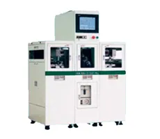
Tape & Reel
Mounted on the tape-and-reel packer, the last step before shipping. Checks lead quality, reads the index hole on the mould face, and verifies the mark printed on the package before it is taped.
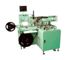
Tray Sorting
Reads the character stamped on the tray tab by OCR and reports it to the server. A line-scan camera then covers the whole tray at once, checking every pocket for package presence, position and EMC surface marking, and sorts on the result.
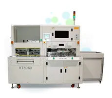
BGA Singulation
Fitted to the press that separates individual packages from a BGA frame. Three inspections run together — mark vision reads the brand and traceability marking, ball vision checks the balls on each separated package, and chip vision checks chip size and surface condition.

BGA Saw & Sort
Fitted to the machine that saws a CSP frame into individual packages and arranges them into trays. Inlet vision confirms the strip is loaded the right way round before sawing; ball vision checks ball presence, quality and position along with package size; mark vision checks the marking.
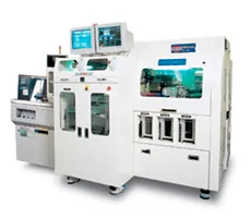
Laser Drilling
Three roles around the laser. ID vision reads the select mark on the PCB face and sends good and reject positions to the laser system. Align vision measures position and angle offset so the hole lands on target in the mould face. QC vision then checks the drilled hole along with the balls and pad face.
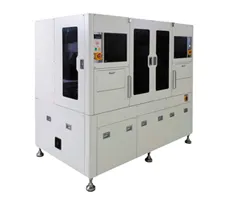
Off Loader BGA Ball
On the machine that loads reflowed frames into magazines after ball attach. Checks whether each ball is present and measures its quality, position and size.
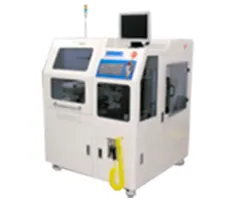
BGA Ball Attach
Runs before and after balls are placed on a CSP frame. Align vision measures the offset in position and angle between ball tool and PCB and sends the correction to the machine so the balls land on the pads; ball tool vision checks the balls held on the tool; a further check follows once they are attached.
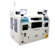
Laser & Ink Marking
ID vision reads the select mark on the PCB face to give the marking machine its position data, and reads the 2D barcode to report frame information to the server. Mark vision then verifies the marking on the package. Fits a range of IC marking machines and inspects before and after marking.